The SynthLab-DX example demonstrates how to use the sinusoidal wavetable and EG together to create four FM Operators. This shows you how to implement phase modulation between pitched oscillators (the Yamaha DX synths were not truly FM synths, but actually phase modulation (PM) synths, see the synth book for details). The four operators are arranged into eight (8) algorithms identical to the Yamaha DX-100 synth. Once you see how simple it is to implement FM/PM across oscillators, you may add more operators and algorithms to your own designs. The DX interface is substantially different than the rest of the synth examples because of the added controls for the operator's EG.
The DX synth here uses only sinusoids as the carrier and modulator signals, and uses a single sinusoidal wavetable for all pitched oscillator implementations, exactly as the Yamaha DX line of products. There is only a single FM oscillator core, that renders that solitary sinusoid. You are encouraged to try different waveforms here to understand the ramifications as well as the reasoning for only using sinusoids (HINT: the Fourier Transform solution to the modulation equation is only known for sinusoids. Other waveforms will alias madly so be aware!)
The modulation matrix is formatted as a "pin programmable" control, reminiscent of the EMS VCS3. Note that the ModulationMatrix C++ object is designed for a variety of different interfaces with intensity controls and internal switches that will work with practially any mod matrix scheme. For all SynthLab examples, the filterEG -> filter fc routings are pre-enabled and the source and destination intensities are set to 0.75 so that you will hear the effects in the first patch. This panel also includes the ping-pong delay controls.
Figure 1 shows the Voice Edit and Mod Matrix interface panels for the DX synth. You may recognize the colors from the original Yamaha DX packaging whose colors were lifted to render the GUI.
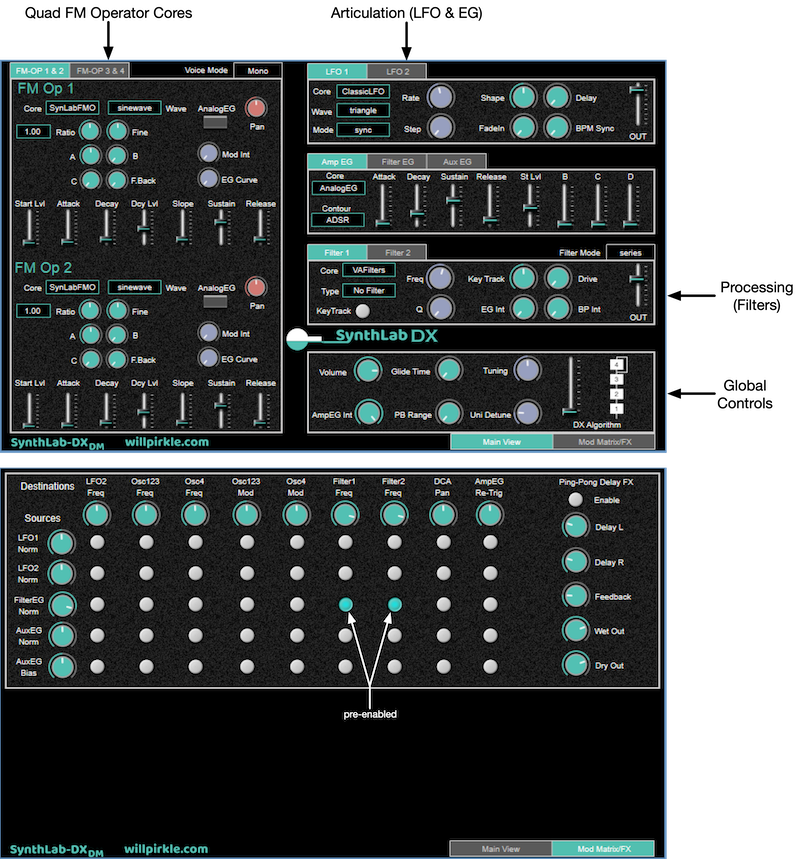
Figure 1. SynthLab-DX Interface
FM Operator Controls
Figure 2 shows a variety of options for the DX synth that do not exist for the others. The synth book explains the three different EGs used in the projects. The DX FM Operator uses the DXEG object that has an extra segment named "slope" that requires a decay level setting. This slope control allows you to create FM patches that swell up or down with harmonic content prior to landing at the sustain level. The DX EG may be set as linear, exponentially curved, or any combination using the "EG Curve" control. The added slope and decay level setting may cause a brief jump in level if the key is released before the EG hits the sustain level. There is an added analog EG enable button that slots in the analog EG in place of the DX EG. Using this will remove any glitch in the EG and the slope time/decay level controls will be ignored.
With the operator's EG set, you can focus on the other FM controls that have a profound affect on the sound: ratio, modulation intensity (aka "index of modulation" or "FM index") and feedback. The algorithm chooser is at the lower right where a slider choose from the 8 algorithms. Note that in each case, FM Operator 4 is allowed to have self-feedback phase modulation. This is the only operator allowed to modulate itself. However, the controls are avaiable for the other three operators if you would like to impelment that in addition to the normal operator-driven modulation. See the code in the SynthVoice::render( ) function for ideas on implementation.
The FM operator oscillators output in stereo and feature a pan control, which can behave in fun and interesting ways when combined with phase modulation, as the amount of energy in each channel will change the index of modulation in the carrier waveform's channels. When cascaded and using pan modulation, this can have very cool and interesting effects.
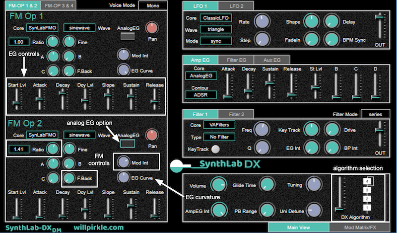
Figure 2: the DX Voice Edit panel is very different from the others and includes added EG controls as well as an algorithm selector in the lower right
Modulation Matrix
Figure 3 shows the modulatiom matrix panel, which is fundamentally identical across all SynthLab synths (there are minor differences for the DX and WS varieties). The destinations are columns and sources are rows. Each source and destination features a single intensity control (see the synth book for alternate modulation matrix schemes). Routings are enabled by pressing the buttons that connect rows and columns. For the DX ynth, the unique modulation is pan-mod. In Figure 3, you can see that LFO2 has been chosen as a modulation source for the "unique modulation" destination and source/destination intensities have been adjusted for operation. This can be tricky to use because it should really only be applied to the final "output" operators in the algorithm. For modulating operators, the stereo outputs are summed together prior to applying the phase modulation, so panning has no real affect on them. See the synth book for more information.
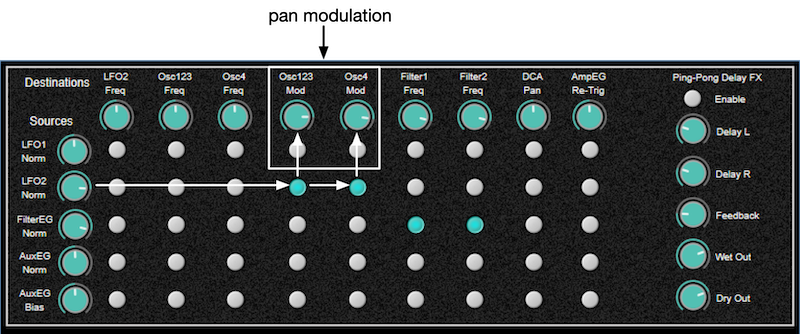
Figure 3: SynthLab-DX modulation matrix panel with LFO2 selected for the oscillator unique modulation