SynthLab SDK
Modify the LFO Core

We will modify the LFOCore object by adding a new waveform to it. The new waveform will be a clipped sinusoid whose top and bottom 1/4 waveform will be clipped off. You will learn how the SynthClock can be used to render trig functions in this simple tutorial.


clipsine.png


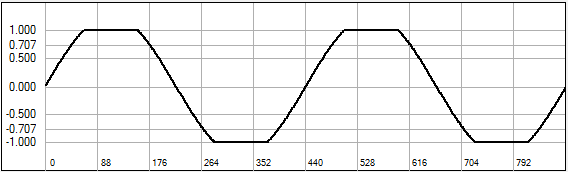
Figure 1: waveform of clipped-sine LFO

Constructor: Waveform Names
Open the LFOCore.cpp file and check out the constructor. Notice that only the first 10 (index 0 - 9) of the waveform strings are populated. We will add our clipped sine as the waveform indexed with 10. Note that the empty_string.c_str() produces the output "-----" which the user percieves as empty or non-existent.

LFOCore::LFOCore()
{
moduleType = LFO_MODULE;
moduleName = "ClassicLFO";
lookupTables.reset(new(BasicLookupTables));
// --- our LFO waveforms //"clip sine";//
/*
Module Strings, zero-indexed for your GUI Control:
- triangle, sine ,ramp_up, ramp_dn, exp_up, exp_dn, exp_tri, square, rand_SH1, pluck
*/
coreData.moduleStrings[0] = "triangle"; coreData.moduleStrings[8] = "rand S&H1";
coreData.moduleStrings[1] = "sine"; coreData.moduleStrings[9] = "pluck";
coreData.moduleStrings[2] = "ramp up"; coreData.moduleStrings[10] = "clip sine"; //<-- ADDED WAVEFORM slot 10
coreData.moduleStrings[3] = "ramp dn"; coreData.moduleStrings[11] = empty_string.c_str();
coreData.moduleStrings[4] = "exp up"; coreData.moduleStrings[12] = empty_string.c_str();
coreData.moduleStrings[5] = "exp dn"; coreData.moduleStrings[13] = empty_string.c_str();
coreData.moduleStrings[6] = "exp tri"; coreData.moduleStrings[14] = empty_string.c_str();
coreData.moduleStrings[7] = "square"; coreData.moduleStrings[15] = empty_string.c_str();
// --- modulation control knobs
coreData.modKnobStrings[MOD_KNOB_A] = "Shape";
coreData.modKnobStrings[MOD_KNOB_B] = "Delay";
coreData.modKnobStrings[MOD_KNOB_C] = "FadeIn";
coreData.modKnobStrings[MOD_KNOB_D] = "BPM Sync";
}
//

reset( )
Check out the reset() function which initializes the object. Notice the lfoClock member (declared in the LFOCore.h file) is reset here. This resets the modulo counter for operation (this is detailed in the Synth book). We'll be using the lfoClock's output value (a member named mcounter) shortly.

// --- reset clocks and timers
lfoClock.reset(); //<-- reset the timebase
sampleHoldTimer.resetTimer();
delayTimer.resetTimer();
//

update( )
Move down to the update() function and notice what is fundamentally happening here - the user's parameter settings (from the GUI) and the modulator values are being combined to set the final oscillator frequency for the LFO. A piece of this function is below. Think about what you could change or modify for your own object.

  • notice how the modulation input array's kFrequencyMod slot is accessed and the value used to alter the frequency that the user has set in the parameters structure
  • the newly calculated value is bounded on a range with the boundValue() function which is used throughout SynthLab
  • the lfoClock is updated with the new frequency
// --- apply linear modulation
double modValue = processInfo.modulationInputs->getModValue(kFrequencyMod) * LFO_HALF_RANGE;
// --- apply linear modulation
double newFrequency_Hz = parameters->frequency_Hz + modValue;
boundValue(newFrequency_Hz, LFO_FCMOD_MIN, LFO_FCMOD_MAX);
// --- calculate the phase inc from the frequency
lfoClock.setFrequency(newFrequency_Hz, sampleRate);

render( )
The LFOCore::render operation is broken into three main code chunks. At the top, I work with the delay and fade-in timers and functions that either stave off or change the amplitude of the LFO output. Notice how I get the LFOParameter structure pointer at the top of the function. Watch for the code that enters the loop over the block of data to process

for (uint32_t i = 0; i < processInfo.samplesToProcess; i++)

bool LFOCore::render(CoreProcData& processInfo)
{
// --- parameters
LFOParameters* parameters = static_cast<LFOParameters*>(processInfo.moduleParameters);
// --- one shot flag
if (renderComplete) return true;
for (uint32_t i = 0; i < processInfo.samplesToProcess; i++)
{
// --- delay timer
if (!delayTimer.timerExpired())
{
// --- advance timer
delayTimer.advanceTimer(processInfo.samplesToProcess);
// --- just return the current value
return outputValue;
}
// --- check for completed 1-shot on this sample period
bool bWrapped = lfoClock.wrapClock();
if (bWrapped && parameters->modeIndex == enumToInt(LFOMode::kOneShot))
{
renderComplete = true;
outputValue = 0.0;
return renderComplete;
}
//

The next chunk of code is a big decision-tree, based on the user's selection for the parameters->waveformIndex value and you can see the user of the strongly typed enum.

if (parameters->waveformIndex == enumToInt(LFOWaveform::kSin))
{
// --- calculate normal angle
double angle = lfoClock.mcounter*kTwoPi - kPi;
double sine = parabolicSine(-angle);
outputValue = sine;
}
else if (parameters->waveformIndex == enumToInt(LFOWaveform::kTriangle))
{
outputValue = 1.0 - 2.0*fabs(bipolar(lfoClock.mcounter));
}
// etc...

Add the New Code
Our clipped sinusoid is going to be very naive in design; we will use the trig function sin() to generate the sinusoid and learn about the SynthClock in the process. Please do not send me hate-mail or toxic forum posts about calling the sin( ) function – this is just a tutorial. Later, you can exchange this for one of the sinusoidal approximation functions from the synth book if you like. The SyntClock is a modulo counter. The count variable is named mcounter and you can access it directly; it is used so frequently that I didn't want to waste CPU cycles to call a getter function on a protected member. You may certainly change this if it disturbs you; the class definition is in the synthbase.h file.

The modulo counter will count from 0.0 to 1.0 and rollover. The trig function sin() takes its argument in radians on the range of [-pi, +pi] or [0, 2pi]. Our code will:

  • take the modulo counter value and multiply it by 2pi to generate the argument for the sin() function
  • multiply the outut of the sin() function by 1.25 to amplify it
  • use the boundValue() function to clip the waveform at [-1.0, +1.0]

We know that the waveform index for our new LFO wave is 10 so we can just modify the decision tree directly (you can always add a new value to the enumeration if you like):

// --- calculate the oscillator value
if (parameters->waveformIndex == 10)
{
// --- calculate normal angle
double angle = lfoClock.mcounter*kTwoPi; // scale by 2pi
double sine = 1.25 * sin(angle); // amplify by 1.25
boundValue(sine, -1.0, +1.0); // clip
outputValue = sine; // set output variable
}
else if (parameters->waveformIndex == enumToInt(LFOWaveform::kSin))
{
// --- calculate normal angle
double angle = lfoClock.mcounter*kTwoPi - kPi;
double sine = parabolicSine(-angle);
outputValue = sine;
}
etc...

The last part of the render operation first runs some modifiers on the waveform, one for step quantization and the other for shape and then fashions the variations on the waveforms and plants them into their pre-assigned slots in the modulation output array. Here are the modifications; notice the source of the modifiers, one is a direct parameter member, and the other is a parameter mod knob.

// --- quantizer (stepper)
if (parameters->quantize > 0)
outputValue = quantizeBipolarValue(outputValue, parameters->quantize);
outputValue = quantizeBipolarValue(outputValue, pow(2.0, 10));
// --- scale by amplitude
outputValue *= parameters->outputAmplitude;
// --- SHAPE --- //
double shape = getModKnobValueLinear(parameters->modKnobValue[MOD_KNOB_A], 0.0, 1.0);
double shapeOut = 0.0;
if (shape >= 0.5)
shapeOut = bipolarConvexXForm(outputValue);
else
shapeOut = bipolarConcaveXForm(outputValue);
// --- split bipolar for multiplier
shape = splitBipolar(shape);
outputValue = shape*shapeOut + (1.0 - shape)*outputValue;
//

The modulation output array slots are indexed with an enum that is defined just before the LFOParameters structure (you will notice the same pattern with the rest of the modulation sources). The SynthLab LFO objects output four different values; a normal output plus a -180 degree inverted variation and two unipolar outputs (see the synth book for details).

// --- array locations in mod output
enum {
kLFONormalOutput,
kLFOInvertedOutput,
kUnipolarFromMin,
kUnipolarFromMax,
kNumLFOOutputs
};
//

Here is the last bit of code. Rememeber that we are in a loop, processing a block of rendered output data. Notice how we only write an output on the first sample in the block. This is because SynthLab uses block audio processing and granulized modulator values (see synth book). You can always force the system to process samples rather than blocks by setting the blocksize variable to 1.

// --- set outputs: either write first output or last in block
//
// --- first output sample only:
if (i == 0)
{
processInfo.modulationOutputs->setModValue(kLFONormalOutput, outputValue);
processInfo.modulationOutputs->setModValue(kLFOInvertedOutput, -outputValue);
// --- special unipolar from max output for tremolo
//
// --- first, convert to unipolar
processInfo.modulationOutputs->setModValue(kUnipolarFromMax, bipolar(outputValue));
processInfo.modulationOutputs->setModValue(kUnipolarFromMin, bipolar(outputValue));
// --- then shift upwards by enough to put peaks right at 1.0
processInfo.modulationOutputs->setModValue(kUnipolarFromMax,
processInfo.modulationOutputs->getModValue(kUnipolarFromMax) + (0.5 - (parameters->outputAmplitude / 2.0)));
// --- then shift down enough to put troughs at 0.0
processInfo.modulationOutputs->setModValue(kUnipolarFromMin,
processInfo.modulationOutputs->getModValue(kUnipolarFromMin) - (0.5 - (parameters->outputAmplitude / 2.0)));
}
// --- NOTE: inside the loop, advance by 1
lfoClock.advanceClock();
}
return true;
} // end of render()
//

doNoteOn( ) and doNoteOff
Here are the two MIDI note event handlers. There is nothing for us to change in these functions but you should still check them out because you'll be writing your own soon. The large majority of ModuleCores have empty note-off handlers as there is usually nothing to do; resetting most objects will be redundant with the note-on function.

// --- note on handler
bool LFOCore::doNoteOn(CoreProcData& processInfo)
{
// --- parameters
LFOParameters* parameters = static_cast<LFOParameters*>(processInfo.moduleParameters);
renderComplete = false;
if (parameters->modeIndex != enumToInt(LFOMode::kFreeRun))
{
lfoClock.reset();
sampleHoldTimer.resetTimer();
outputValue = 0.0;
rshOutputValue = noiseGen.doWhiteNoise();
delayTimer.resetTimer();
double delay_mSec = getModKnobValueLinear(parameters->modKnobValue[LFO_DELAY], 0.0, MAX_LFO_DELAY_MSEC);
delayTimer.setExpireSamples(msecToSamples(sampleRate, delay_mSec));
double fadeIn_mSec = getModKnobValueLinear(parameters->modKnobValue[LFO_FADE_IN], 0.0, MAX_LFO_FADEIN_MSEC);
fadeInModulator.startModulator(0.0, 1.0, fadeIn_mSec, processInfo.sampleRate);
}
if (parameters->waveformIndex == enumToInt(LFOWaveform::kTriangle))
lfoClock.addPhaseOffset(0.25);
if (parameters->waveformIndex == enumToInt(LFOWaveform::kRampUp) || parameters->waveformIndex == enumToInt(LFOWaveform::kRampDown))
lfoClock.addPhaseOffset(0.5);
return true;
}
// --- note off handler is empty
bool LFOCore::doNoteOff(CoreProcData& processInfo)
{
return true;
}
//

Now, you can test the new object in your MinSynth C++ object and check to make sure you are getting the clipped output. The waveform here was taken from the output of the LFO; a trick I use all the time to test LFOs is to run them at audio frequencies and pipe their data out to the oscilloscope in RackAFX.


clipsine.png


Next, we will create a new ModuleCore from scratch to implement a pitched oscillator based on the same trig function calls.


synthlab_4.png