The MinSynth object seems simple enough, and it is actually quite a small amount of code for the results you get, but the handling of the modulation values is sloppy at best. In the first iteration of MinSynth I handled modulation like this:
- render the modulators
- find the modulation output values in the object's modulation arrays
- find the modulation input slots for the modulation receivers (destinations)
- write the modulation output values into the appropriate slots in the modulation input arrays
We also saw how intensity controls affected the modulation (Mod Knob D needs to be at 1.0 for the filter to modulate). The ModMatrix object handles these chores and once setup, requires only a single function call to its render( ) method to perform the transfer of information from the modulation sources (LFO and EG) to the modulation destinations (OSC fo and FLTER fc). The connection of a modulation source to a destination is a Modulation Routing or Mod Routing.
The ModulationMatrix object is extremely efficient; when profiling the synths, this object's runModMatrix( ) function was always at the bottom of the CPU percentage list.
Programming the Mod Matrix
You program the matrix by first giving it a set of modulation sources and destinations. This is done with pointers to and from the modulation input and output arrays and is handled in fuction calls. Then, you connect the sources and destinations using optional source, channel and destination intensity controls. You can create hardwired routings that are always present, or you can add and remove routines as the user mainpulates the GUI controls. In this section, we will look at setting up the modulation matrix and creating sources, destinations and hardwired routings. First, decide on the kind of matrix the user will see.
Modulation Matrix Options
The ModMatrix object can support practically any kind of modulation matrix scheme. Two common schemes are showns in Figure 14.3 from the synth book here:
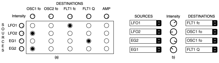
Figure 14.3: modulation matrix designs include (a) pin/button programmable with global source and destination intensity controls and (b) a limited choice matrix with individual channel routing intensity controls
In Figure 14.3 (a) you can see the pin-programmable matrix that the SynthLab projects all use. All sources can be routed to all destinatons with pins that connect row and column cells. In this case, each modulation source has an intenstity control which operates on the final modulator output value, and each destination has an intesity control that governs the strength of the modulation input value. It may be easier to think of these controls as "send" (from the modulation outptu) and "receive" (into the modulation input) controls. SynthLab calles these the Mod Source Intensity and Mod Destination Intensity controls. All intensity controls have ranges from [-1.0, +1.0] where negative values will invert the modulation operation.
In Figure 14.3 (b) you can see another common paradigm for modulation matrix setup. Here, the user is restricted to a set number of modulation routings (4 in total). Hovever, in this case, each routing has its own intensity control. SynthLab calls this the Channel Intensity control for that particular routing.
The SynthLab ModMatrix can implement either of these paradigms, or both at once so that every modulation routing could have a source, channel, and destination intensity control. I do not use the channel intensity controls in SynthLab because I think it would be overwhelming for the user, but it is possible. Figure 14.4 from the synth book is shown below. It shows the routing between a LFO's normal output (slot 0 of its modulation output array) to an oscillator's frequency modulation input (slot 3). Notice the location of the source and destination intensity controls. In this example, this routing is hardwired, and a locked path is setup with a hardwired intensity control. The user does not see these hardwired routing intensity controls. The two most common intensity setups are shown in 14.4 (b) and (c), however it is possible to have still other combinations of intensity controls.

Figure 14.4: (a) the ModMatrix configuration for a single routing shows the multiple intensity controls and enable-switches; here the hardwire enable is overriding the channel branch (b) and (c) show the configurations that match Figure 14.3 (a) and (b) respectively
Mod Sources/Destinations
The next step is to decide on your sources and destinations. For our MinSynth, we will choose a few modulation source values (there are many more than you may think, so check the docuementation and sample code!) and choose a few modulation destination values. The LFOs are also destinations, so you can modulate one LFO with another, or even with itself! These sources and destinations will mimic the last version of MinSynth.
Modulation Sources
There are two common modulation sources used in all of the SynthLab example products, plus one for the WaveSequencing synth:
- LFO normal output
- EG normal output
- Wave Sequencer's multi-lane outputs
Modulation Destinations
For our MinSynth, we will choose a few modulation destination values. The LFOs are also destinations, so you can modulate one LFO with another, or even with itself! Our destinations will be:
- Oscillator frequency modulation (bipolar)
- Filter cutoff frequency modulation (bipolar)
- DCA EG modulation (unipolar)
Add the Object
Now we'll add the modulation matrix object to the MinSynth, first adding the files to the compiler project:
Next, be aware that the ModMatrix parameter structure contains functions for performing the routing and hardwiring. This is because usually, these are results of GUI manipulations and need to be set from a GUI message handler. The sequence of steps for setting up the ModMatrix object are:
- create the ModMatrix; if standalone pass a nullptr for the ModMatrixParameters
- clear the matrix arrays
- add the sources: you give the matrix pointers to modulation source locations within each object's ModulationInput array
- add the destinations: you give the matrix pointers to modulation destination locations within each object's ModulationOutput array
- Add any hardwired routings; the most common is for the AmpEG -> DCA EG input
So, you can modify the MinSynth object with the ModMatrix and setup code:
Add Sources/Destinations & Hardwired Routings
Next, in the MinSynth constructor, create the ModMatrix and setup the sources, destinations, and hardwired routings. Notice how you get pointers to the input and output modulation arrays from the various components. The constants here (kSourceLFO1_Norm, kDestFilter1_fc_Bipolar, etc...) denote the slots in the modulation arrays and are found in synthconstants.h in the enum modDestination and enum modSource enumerations. You can add as many sources and destinations as you like to these enumerations. The mod matrix array rows and columns will grow accordingly.
Running the Matrix
Now, we can re-write the render( ) function and remove all of the manual modulation routing code. It will all be replaced by one single function call to the ModMatrix::runModMatrix( ) method! Notice how simple and compact the resulting render code becomes.
Updating the ModMatrix from a GUI
The ModMatrix object has multiple functions for updating its routings that are easy to use. The main thing to rememeber is that everything references the source and destination array slot constants such as kSourceLFO1_Norm, kSourceAmpEG_Norm, and kDestFilter1_fc_Bipolar. Notice that these define the sources and destinations, and when used as a pair of values, they define a particular modulation routing.
Modifying Intensity Controls
The ModMatrix includes three intensity controls for each routing, along with a hidden hardwired intensity that is setup once and does not change. Notice that you do NOT need to implement all three intensity controls - in fact, you can create a mod matrix that has no intensity controls whatsoever, and use the modulator output controls (LFO output amplitude) for source intensities, and hardwire the rest. These functions are easy to understand and relatively self-explanatory. The code below would go into your update( ) function that is called as a result of GUI manipulation.
Enable/Disable Channel Routings
You use the source/destination constants in pair-wise form to enable or disable a channel routing:
Default Destination Values
Each destination has an initial value that is applied when the matrix is created - this is called the "default value." Normally, this value is 0.0 which represents no modulation. On occasion, you may want to preset the default to a non-zero value; this is often needed to prevent something from appearing to not work when the first note event occurs. You can set any destination's initial value using the simple function:
Adding or Removing Sources/Destinations During Synth Operation
The ModMatrix object allows you to add or remove sources or destinations while the synth is operational, and after construction has occurred. While this is not an ordinary operation, it is still do-able using two functions to clear the routings. As with the other ModMatrix functions, the source/destination constants are used to indicate the row or column slot to clear:
Mod Destination Transforms
On occasion, you will need to have the matrix apply a transform to the destination modulation value; this is often done to change the modulation from unipolar to bipolar. See the MMA DLS Level I or II specifications for more information on transforms. When you add a modulation destination, you have the option of supplying a transform constant that will automatically be applied to the final destination value. SynthLab has two built-in transforms (plus a no-transform specifier) declared in synthconstants.h, and of course you may add more and modify the runModMatrix( ) function to apply them. You will find the transforms applied to the EG re-trigger modulation which must be unipolar.
Summary of ModMatrix and ModMatrixParameter Functions
This table list the functions that the matrix and its parameters expose, and their usage. See the sample project code for more details and examples.
ModMatrix Functions:
| ModMatrix Function | Description |
|---|---|
| addModSource | add a source, supply the modulation array index (constant) and pointer to the array |
| addModDestination | add a destination, supply the modulation array index (constant) and pointer to the array |
| clearModSource | remove a source, supply the modulation array index (constant) |
| clearModDestination | remove a destination, supply the modulation array index (constant) |
| clearModMatrixArrays | clear all sources and destinations at once |
| runModMatrix | run the matrix, which connects sources to destinations and applies intensity controls |
ModMatrixParameter Functions:
| ModMatrixParameter Function | Description |
|---|---|
| setMM_SourceIntensity | set source intensity value, supply the modulation array index (constant) and value [-1, +1] |
| setMM_DestIntensity | set destination intensity value, supply the modulation array index (constant) and value [-1, +1] |
| setMM_ChannelIntensity | set channel intensity value, supply the source and destination modulation array indexes (constants) and value [-1, +1] |
| setMM_DestHardwireIntensity | sets a hardwired channel intensity value, same arguments as setMM_ChannelIntensity |
| setMM_ChannelEnable | enable/disable a modulation routing, same arguments as setMM_ChannelIntensity |
| setMM_HardwireEnable | enable/disable a hardwired modulation routing, same arguments as setMM_ChannelIntensity |
| setMM_DestDefaultValue | set the initial default destination modulation value if non-zero |
| setMM_HardwiredRouting | make a complete hardwired routing with source, destination and default channel intensity |
| setMM_DestHighPriority | sets a high-priority flag for modulation routings that are not granulized (not used in SynthLab) |